

- 8.62 MB
- 2021-04-15 发布

2/16/2021 1:06 AM
Slide
1
差速原理
2/16/2021 1:06 AM
Slide
2
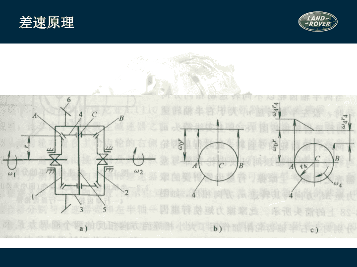
差速原理
A、B、C
三点的圆周速度相等:
r
v
0
w
=
2/16/2021 1:06 AM
Slide
3
差速原理
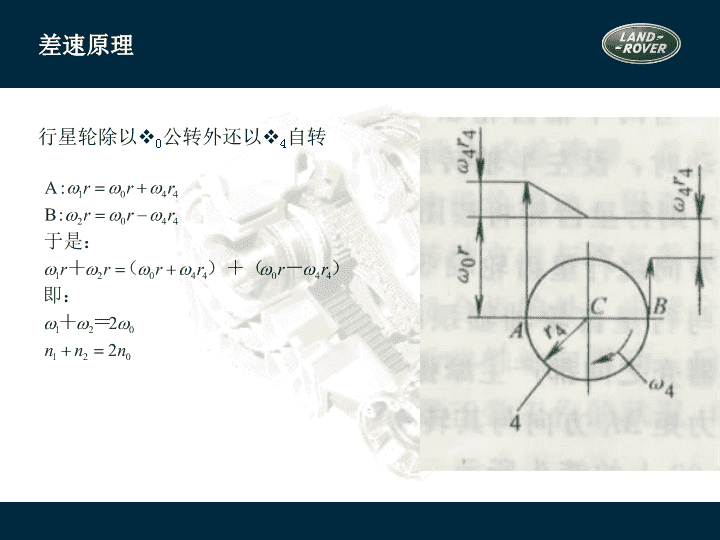
行星轮除以
0
公转外还以
4
自转
运动特性方程式
2/16/2021 1:06 AM
Slide
4
当任何一侧半轴齿轮的转速为零时,另一侧半轴齿轮的转速为差速器壳转
速的两倍
当差速器壳转速为零(例如用中央制动器制动传动轴)时,若一侧半轴齿
轮受其它外来力矩而转动,则另一侧半轴齿轮即以相同转速反相转动
2/16/2021 1:06 AM
Slide
5
对称式锥齿轮差速器中的转矩分配
行星齿轮没有自转时
M
1
=M
2
=M
0
/2
当两半轴齿轮以不同转速向相同方向转动时:设n
1
>n
2
,M
r
为差速器的内摩擦力矩,可近似得到
M
1
=(M
0
-M
r
)/2
M
2
=(M
0
+M
r
)/2
M
2
- M
1
=M
r
2/16/2021 1:06 AM
Slide
6
锁紧系数K
为了衡量差速器内摩擦力矩的大小及转矩的分配特性,以锁紧系数K表示
一般 K=0.05~0.15,K
b
=1.1~1.4; 可以认为无论左右驱动轮转速是否相等,其转矩基
本上总是平均分配的
2/16/2021 1:06 AM
Slide
7
强制锁止式(差速锁)差速器
斯堪尼亚
LT110
型汽车
差速锁组成:
接合器及操纵装置
优点:
结构简单,易于制造
缺点:
操纵不便,出现与无差速器时相同的问题
9-外接合器,10-内接合器
2/16/2021 1:06 AM
Slide
8
高摩擦自锁式差速器
摩擦片式自锁差速器
滑块凸轮式差速器
2/16/2021 1:06 AM
Slide
9
摩擦片式自锁差速器
K:0.6~0.7
2/16/2021 1:06 AM
Slide
10
托森差速器
2/16/2021 1:06 AM
Slide
11
托森差速器的结构
2/16/2021 1:06 AM
Slide
12
n
1
=n
2
n
1
=n
2
=n
0
M
1
+M
2
=M
0
2/16/2021 1:06 AM
Slide
13
n
1
n
2
n
0
0
2/16/2021 1:06 AM
Slide
14
转矩分配原理
托森差速器是利用蜗杆传动副的高内力矩M
r
进行转矩分配的
设n1>n2, 转矩分配为:
M
1
=M
0
-M
r
M
2
=M
0
+M
r
当n2=0,相当于差速器锁死
2/16/2021 1:06 AM
Slide
15
2/16/2021 1:06 AM
Slide
16
粘性联轴差速器
壳体
传动轴
传动轴
内叶片(花键轴传力片)
外叶片(壳体传力片)
传力毂
2/16/2021 1:06 AM
Slide
17
粘性联轴器的工作介质
硅油
粘度稳定性好
抗剪切性好
抗氧化、低挥发和闪点高
传递扭矩时温升可达200°,内压可达100KPa(在壳体内封装10%~20%空气)
具有高爬行性,密封有一定难度
2/16/2021 1:06 AM
Slide
18
粘性联轴器工作原理与特点
利用油膜剪切传递动力
其传递的转矩与与硅油的密度、粘度、主传动轴转速差、内叶片数和半径等
成正比;与内外叶片间的间隙成反比。
输入轴与输出轴的转速差越大,由输入轴传递到输出轴的转矩就越大
粘性联轴器又称粘性联轴的差速器,主要用于轴间差速器。用于轮间差速器时
称限滑式差速器(LSD)
2/16/2021 1:06 AM
Slide
19
桥壳
功用
支承并保护主减速器、差速器和半轴并使左右驱动轮的轴向相对位置固定
与从动桥一起支承车体的总重量
承受车轮传来的路面反作用力和力矩,经悬架传给车架
从结构上可分成两类:整体式桥壳, 分段式桥壳
根据整体式桥壳制造方法的不同又可分为:整体铸造,钢板冲压焊接,中间铸造压入钢
管形式
2/16/2021 1:06 AM
Slide
20
智能技术(L319)
地形反馈适应系统
地形反馈适应系统是路虎的新发明,并首次应用在发现
3
上。
传统的越野驾驶需要驾驶员有丰富的越野驾驶经验,比如,锁止差速器或关闭
DSC
。地形反馈适应系统帮助驾驶员选择电子系统,为适应不同的地形,只要
驾驶员控制方向盘就可以了。没有多少越野驾驶经验的驾驶员也可以越野了。
可以说地形反馈适应系统是
“
一
个
在
车内随时相伴
的
驾驶专
家
”
。
碰到不同的地形
,
驾驶
要如何
处
理
…
2/16/2021 1:06 AM
Slide
21
智能技术(L319)
路面
状况
面
临
的挑
战
要如何
处
理
草地或雪地路
况
非常滑
,
轮
胎容易空轉
转
打到高
挡
位
;
轻
踩油
门
;
锁
定中央差速器
泥
泞
且凹陷
沟
槽
路面
轮
胎打滑
;
轮
胎循跡力降低
;
而且
无
法
轻
易辨別
轮
胎的方向
加力箱切
换
到低
齿
比
;
升高底
盘
;
轻
踩油
门
;
锁
定中央差速器
;
方向
盘
打
直
沙土路面
车
子容易陷入沙
里
加力箱
设
定在高
齿
比
;
锁
定中央差速器
;
采
取
积极
的
动
力輸出
;
关闭
DSC
系统
和
ABS
系统
岩石路面
必須有足
够
的底
盘离地空间
低速行駛
;
随时
注意
车辆
的底
盘离地空间
2/16/2021 1:06 AM
Slide
22
智能技术(L319)
地形
反馈适应系统
可以
针对
不同的路
况对
以下不同系
统
做出
适当
的
调
整
:
EMS
发动机管理系统
全
时
四
通道
ABS
防抱死系统
EBD
电子制动力分配
系
统
ETC
四
轮电子牵引力
控制系
统
DSC
动态稳定控制
系
统
HDC
陡坡缓降控制系统
手自动变速箱
空气悬挂
2/16/2021 1:06 AM
Slide
23
智能技术(L319)
控制旋
钮让驾驶员
可以自由
选择
以下
几种
模式
:
正常模式
草地
/
砾
石地
/
雪地模式
泥
泞
地
/
湿
滑凹陷
轮沟
路面模式
沙地模式
巨石地形蠕行模式
从一种模式转换到另一种模式只要几秒钟
的时间,以致驾驶员几乎感觉不到。
2/16/2021 1:06 AM
Slide
24
EMS
自动变速箱
路面
状况
地形
反馈适应系统会
如何
帮
助
驾驶员
草地或雪地
泥
泞与
凹陷
沟
槽路面
沙土路面
岩石路面
更平
缓
增加的扭
矩传递
以避免
车轮
生打滑
漸
进
式的扭
矩传输
更
积极
的油
门
反
应
谨慎细微
的扭
矩传输
,
以便
车速
能
够获
得良好控制
以二
挡
起步
(
高
齿
比
)
或是以三檔起步
(
低
齿
比
)
且提早升
挡
适时变换挡
位
,
以配合泥
泞
地
驾驶状况
在每
个挡位会
停留
较
久
,
并倾
向
更迅速地
降
挡
以一
挡
起步
,
延迟
升
挡
智能技术(
L319
)
2/16/2021 1:06 AM
Slide
25
加力箱模式
差速器
路面
状况
地形
反馈适应系统会
如何
帮
助
驾驶员
草地或雪地
泥
泞与
凹陷
沟
槽路面
沙土路面
岩石路面
智能技术(
L319
)
高
齿
比或低
齿
比
低
齿
比
高
齿
比或低
齿
比
高
齿
比或低
齿
比
增
加
预
先
负载
接合
增
加
预
先
负载
接合
,
且
对于
打滑
现
象有更
积极
的反
应
一般
状况
增加
预先负载
接合
,
且
对于
打滑
现
象有更
积极
的反
应
2/16/2021 1:06 AM
Slide
26
ETC
/DSC
空气悬挂
路面
状况
地形
反馈适应系统会
如何
帮
助
驾驶员
草地或雪地
泥
泞与
凹陷
沟
槽路面
沙土路面
岩石路面
智能技术(
L319
)
对于打滑现象在极高的敏感度
会适当
修正
DSC
系統
,
以降低
对发动机
輸出的干
扰
越野模式
越野模式
越野模式
越野模式
对于打滑现象在极高的敏感度
对于打滑现象在极高的敏感度
2/16/2021 1:06 AM
Slide
27
创新技术(L320)
地形反馈适应系统
地形反馈适应系统是路虎的新发明,并首次应用在发现
3
上。
传统的越野驾驶需要驾驶员有丰富的越野驾驶经验,比如,锁止差速器或关闭
DSC
。地形反馈适应系统帮助驾驶员选择电子系统,为适应不同的地形,只要
驾驶员控制方向盘就可以了。没有多少越野驾驶经验的驾驶员也可以越野了。
可以说地形反馈适应系统是
“
一
个
在
车内随时相伴
的
驾驶专
家
”
。
碰到不同的地形
,
驾驶
要如何
处
理
…
2/16/2021 1:06 AM
Slide
28
创新技术(L320)
路面
状况
面
临
的挑
战
要如何
处
理
草地或雪地路
况
非常滑
,
轮
胎容易空
转
打到高
挡
位
;
轻
踩油
门
;
锁
定中央差速器
泥
泞
且凹陷
沟
槽
路面
轮
胎打滑
;
轮
胎循跡力降低
;
而且
无
法
轻
易辨別
轮
胎的方向
加力箱切
换
到低
齿
比
;
升高底
盘
;
轻
踩油
门
;
锁
定中央差速器
;
方向
盘
打
直
沙土路面
车
子容易陷入沙
里
加力箱
设
定在高
齿
比
;
锁
定中央差速器
;
采
取
积极
的
动
力輸出
;
关闭
DSC
系统
和
ABS
系统
岩石路面
必須有足
够
的底
盘离地空间
低速行駛
;
随时
注意
车辆
的底
盘离地空间
2/16/2021 1:06 AM
Slide
29
创新技术(L320)
地形
反馈适应系统
可以
针对
不同的路
况对
以下不同系
统
做出
适当
的
调
整
:
EMS
发动机管理系统
全
时
四
通道
ABS
防抱死系统
EBD
电子制动力分配
系
统
ETC
四
轮电子牵引力
控制系
DSC
动态稳定控制
系
统
HDC
陡坡缓降控制系统
手自动变速箱
空气悬挂
2/16/2021 1:06 AM
Slide
30
创新技术(L320)
控制旋
钮让驾驶员
可以自由
选择
以下
几种
模式
:
正常模式
草地
/
砾
石地
/
雪地模式
泥
泞
地
/
湿
滑凹陷
轮沟
路面模式
沙地模式
巨石地形蠕行模式
从一种模式转换到另一种模式只要几秒钟的时
间,以致驾驶员几乎感觉不到。
2/16/2021 1:06 AM
Slide
31
EMS
自动变速箱
路面
状况
地形
反馈适应系统会
如何
帮
助
驾驶员
草地或雪地
泥
泞与
凹陷
沟
槽路面
沙土路面
岩石路面
更平
缓
增加的扭
矩传递
以避免
车轮
生打滑
漸
进
式的扭
矩传输
更
积极
的油
门
反
应
谨慎细微
的扭
矩传输
,
以便
车速
能
够获
得良好控制
以二
挡
起步
(
高
齿
比
)
或是以三檔起步
(
低
齿
比
)
且提早升
挡
适时变换挡
位
,
以配合泥
泞
地
驾驶状况
在每
个挡位会
停留
较
久
,
并倾
向
更迅速地
降
挡
以一
挡
起步
,
延迟
升
挡
创新技术
(L320)
2/16/2021 1:06 AM
Slide
32
加力箱模式
差速器
路面
状况
地形
反馈适应系统会
如何
帮
助
驾驶员
草地或雪地
泥
泞与
凹陷
沟
槽路面
沙土路面
岩石路面
创新技术
(L320)
高
齿
比或低
齿
比
低
齿
比
高
齿
比或低
齿
比
高
齿
比或低
齿
比
增
加
预
先
负载
接合
增
加
预
先
负载
接合
,
且
对于
打滑
现
象有更
积极
的反
应
一般
状况
增加
预先负载
接合
,
且
对于
打滑
现
象有更
积极
的反
应
2/16/2021 1:06 AM
Slide
33
ETC
/DSC
空气悬挂
路面
状况
地形
反馈适应系统会
如何
帮
助
驾驶员
草地或雪地
泥
泞与
凹陷
沟
槽路面
沙土路面
岩石路面
创新技术
(L320)
对于打滑现象在极高的敏感度
会适当
修正
DSC
系統
,
以降低
对发动机
輸出的干
扰
越野模式
越野模式
越野模式
越野模式
对于打滑现象在极高的敏感度
对于打滑现象在极高的敏感度
2/16/2021 1:06 AM
Slide
34
创新技术(L320)
分动箱、中央和后差速器是四驱系统的主要元件。
揽胜运动版在这三个元件上集成了许多新技术,使
车有很好的公路性能,又有出色的越野性能。
分动箱内有一个电子控制的差速器锁。
后差速器锁是选装件。
2/16/2021 1:06 AM
Slide
35
创新技术(L320)
电
子控制差速器的
优点
:
负载
接合
预设
功能
:
可以切
换
到事先
预设
的差
速
比
锁
定
可
变
式扭
矩延展
管理
系统:
在越野
状态
下可
根据
需要
增
加差速
锁
定的
扭矩
为达
到最佳的舒
适状态,
可以降低差速
锁
定的
扭
矩
2/16/2021 1:06 AM
Slide
36
全地形反馈系统
(L319)
培训目标:
了解电子和机械部件的位置
了解系统的优点
理解地形反馈适应系统的工作原理
描述车辆各系统之间的交互作用
EMS
自动变速箱
刹车系统
后差速器
描述部件更换的步骤
/
诊断
知道维修须知
2/16/2021 1:06 AM
Slide
37
空气悬挂模块
仪表
地形反馈适应系统控制模块
后差速器控制模块
后差速器
分动箱
ECM
分动箱控制模块
自动变速箱控制模块
ABS
模块
地形反馈适应系统
2/16/2021 1:06 AM
Slide
38
地形反馈适应系统
系统允许驾驶员针对不同的地形和条件选择相应的程序,以获得最合适的牵引力
程序可以通过位于中控台上的旋钮来选择
控制旋
钮可以选择以
下模式
:
草地/砾
石
路/
雪地模式
泥
泞
地
/湿
滑凹陷路面模式
沙地模式
巨石
爬
行模式
特殊程序关闭
2/16/2021 1:06 AM
Slide
39
地形反馈适应系统
地形反馈适应系统控制旋钮
高
/
低档开关
空气悬挂升降开关
控制模块
5.
特殊模式关闭
6.
草地
/
砾
石
路
/
雪地模式
7.
泥
泞
地
/
湿
滑凹陷路面模式
8.
沙地模式
9.
巨石地形蠕行模式
10. HDC
开关
4
控制模块位于中控台下
360
°
2/16/2021 1:06 AM
Slide
40
概 述
地形反馈适应系统针对不同地形会对以下系统进行调整
:
发动机
管理系统
自动变速箱
分动箱
(
中央差速器
)
后差速器
(
电子
)
刹车系统
(ABS/DSC/ETC/HDC
功能
)
地形反馈适应系统总是激活的
注
: 特殊
程序须提前选择。不要认为可以用它来让已经陷入困境的车辆驶出困境。
2/16/2021 1:06 AM
Slide
41
地形反馈适应系统
发动机管理系统
(EMS)
每
个程序控制相对于油门踏板运动的百分比的扭矩输出
每
选择一个程序,系统会激活一组不同的驾驶参数
注: 发
动机扭矩和转速的变化大约需要
30
秒的时间,这不会被认为是系统 错误。
系统
要确保任何路面下任何程序安全工作,即使选择了不合适的程序
2/16/2021 1:06 AM
Slide
42
地形反馈适应系统
变速箱控制
变速箱控制模块针对每一个程序来改变换档图。升、降档早或晚
在湿滑路面上,系统会选择,比如:
采用高速二档或低速三档来使车辆的打滑最小
2/16/2021 1:06 AM
Slide
43
地形反馈适应系统
变速箱控制
巨石爬行模式
(
低速档
) ,
选择
1
档
,
悬挂高度升高
, 取消DSC
,油门踏板响应重新调整
只有当分动箱处于高速档时,才可以选择变速箱的运动模式
分动箱低速档和地形反馈适应系统处于特殊程序模式时,运动模式不起作用
当
用
CommandShift
手动换档时,变速箱将不自动换档
2/16/2021 1:06 AM
Slide
44
地形反馈适应系统
分动箱和电子后差速器
分动箱和电子后差速器当作一个系统看待
扭矩锁止和差速器锁止,取决于所选的程序和地形条件
锁止的扭矩是通过其它系统的信号来计算的,
例如
发动机负荷
油门踏板位置
变速箱档位
转向角度
车速
横向加速度
旋转加速度
2/16/2021 1:06 AM
Slide
45
地形反馈适应系统
正常模式
相关系统将会适当地调整以适应主要条件的变化
该模式适合于干硬的公路或越野路面
2/16/2021 1:06 AM
Slide
46
地形反馈适应系统
草地/砾
石
路/
雪地模式
该模式适用于表面覆盖了水,粘土,草,雪,疏松的沙硕或沙子的坚硬沙硕路面
.
也适用于冰雪路面
2/16/2021 1:06 AM
Slide
47
地形反馈适应系统
泥
泞-
凹陷路面模式
该模式适用于泥泞、深沟,疏松或者不平的路面
驾驶员可在高速或低速档
选择
该模式,但推荐在低速档选择该模式
驾驶员可通过信息中心的提示正确地选择该模式
车身将会自动升高
2/16/2021 1:06 AM
Slide
48
地形反馈适应系统
巨石爬行模式
该模式不同于湿滑,或干燥坚硬的路面
,
它要求车轮的行程要大,要谨慎
只能在低速档选择该模式
该
程序用系统控制设定来优化悬挂和牵引系统,以满足悬挂极度铰接和低速控制的需要
2/16/2021 1:06 AM
Slide
49
地形反馈适应系统
沙土路面
该模式适用于干燥的沙地
/
沙滩
/
沙丘
/
沙漠
也适用于深砾石路面
在潮湿的或浸水的沙土路面,关闭
DSC
功能将更有利于车辆的行驶
2/16/2021 1:06 AM
Slide
50
地形反馈适应系统
DSC/ABS控制
ABS
的
DSC
控制功能会不顾地形反馈适应控制、分动箱和差速器控制。
DSC
起作用时,会减少锁止扭矩
2/16/2021 1:06 AM
Slide
51
地形反馈适应系统
没使用合适的模式
没选择合适的模式不会危及到驾驶员,或对车辆造成损坏
信息中心将会提示驾驶员选择合适的模式
每种模式的连续使用会减少某些部件的寿命
由于
扭矩的不对称分配,驾驶员可能会感到车辆的响应减少
2/16/2021 1:06 AM
Slide
52
地形反馈适应系统
没使用合适的模式
地形反馈适应系统模块记录了车辆在所有特殊模式下行驶的里程和时间
可用
T4
调出该信息,对顾客关注的问题进行诊断。
例如
:
油耗高
轮胎
过
度磨损
2/16/2021 1:06 AM
Slide
53
地形反馈适应系统
驾驶员信息
信息中心显示
:
当前选择的程序
建议或警告信息
(
确保正确使用各模式
)
转向角
( 避免
泥潭、方向打死时车辆沉陷
)
当前档位和推荐使用的档位
(
比如,打滑的情况下
)
由高速档到低速档档位切换信息
2/16/2021 1:06 AM
Slide
54
地形反馈适应系统
诊 断
地形反馈适应系统模块能够检测和记录故障码
与地形反馈适应系统相关的子系统和仪表也会记录相关的信息
地形反馈适应系统模块记录了车辆在高
/
低档、不同模式下行驶的里程和时间
所有模式下行驶的里程和时间可用
T4
调出
2/16/2021 1:06 AM
Slide
55
地形反馈适应系统
诊 断
地形反馈适应系统工作正常与否取决于相关子系统是否正常工作
如果有一个子系统失效,地形反馈适应系统将不起作用
如果相关子系统没有故障,只需检查地形反馈适应系统控制模块和旋钮
2/16/2021 1:06 AM
Slide
56
分动箱 (
L319
)
2/16/2021 1:06 AM
Slide
57
分动箱组成部件
仪
表
挡位选择开关
分动箱
CJB
输出轴速度传感器
挡位位置传感器
分动箱控制模块
2/16/2021 1:06 AM
Slide
58
概 述
制造商
: Magna Steyr Powertrain – Graz Austria
最大重量:
41.55 Kg
(包括油)
润滑油:壳牌
ATF 3403 M 115 1.5 L
换油间隔:
75.000
英里
适用于所有
T5
底盘的车辆
两速分动箱,带同步‘Shift-on-move’装置
由高速挡换到低速挡,最高时速
16 Kph
由低速挡换到高速挡,最高时速
48 Kph
2/16/2021 1:06 AM
Slide
59
概 述
结构
:
铝外壳
内置油泵
中央差速器
离合器控制机构
2/16/2021 1:06 AM
Slide
60
概 述
特征
:
两
挡:高速挡和低速挡
加强了行驶换挡功能
前、后轴不对称扭矩分配
2/16/2021 1:06 AM
Slide
61
概 述
功能
:
分动箱提供了两个基本功能
:
高
速挡和低挡挡的选择,优化了车辆的公路和越野性能
智能
控制差速器,控制采用了多片式湿式离合器,使车辆有出色的牵引
力和稳定性
2/16/2021 1:06 AM
Slide
62
概 述
恒时四轮驱动,加开式差速器
,
扭
矩永远是
50:50
分配
电
子控制
湿式离
合器
可使分配到
前
轴
和
后轴的扭矩不同
离合器控制可提供以下功能
:
负载功能,随着驱动扭矩的增加,增加锁止扭矩
打滑控制
在越野时,如有需要可增加锁止扭矩
为达
到最佳的舒
适状态,
可以
减小锁止,例如,在停车的时候
2/16/2021 1:06 AM
Slide
63
分动箱动力传递
输入
前部输出
后部输出
2/16/2021 1:06 AM
Slide
64
系统元件
油泵
内置油泵,由输入轴驱动
链条驱动
链条将动力从中央差速器转换到前输出法兰
分动箱
PWM
直流电机
:
电机工作:
高、低速
差速器锁
多片离合器
(
扭矩不对称分配
)
缺省为开式差速器
(
不带锁止
)
2/16/2021 1:06 AM
Slide
65
分动箱换档电机
离合器电机
位置传感器
输入轴
前桥
后桥
离合器接合
(
扭矩
50:50
分配
)
正常驾驶模式
输入轴
前桥
后桥
离合器打滑
(
开式差速器
)
低速行驶
扭矩减小
扭矩增加
2/16/2021 1:06 AM
Slide
68
分动箱换档电机
DC
电机由
PWM
信号控制
位于分动箱的后面
8
针的电气插头
内有位置传感器监测旋转运动
集成温度传感器
提供以下动作:
高
/
低档
多片离合器的动作
Clutch control
换档电磁阀
高速档
/
低速档
高低档选择
2/16/2021 1:06 AM
Slide
70
高低档转换
中央差速器
:
换档接合套
换档拨叉
换档凸轮
高速
低速
2/16/2021 1:06 AM
Slide
71
中央差速器
中央差速器
:
低速档齿比
2.93:1
,以有更低的爬
行速度
高速档齿比
1:1
,直接驱动
2/16/2021 1:06 AM
Slide
72
中央差速器
中央差速器
:
同步器壳体和弹簧
大行星轮
差速器支架
小齿轮
小齿轮轴
小行星齿轮
小行星齿轮轴
太阳轮
差速器壳
差速器侧齿轮
多片离合器壳
犬齿
Clutch control
离合器控制
换档电磁阀
离合器
离合器
2/16/2021 1:06 AM
Slide
74
离合器机构
多片离合器
:
模块监测动作命令
在行驶中主动控制扭矩
防止过度打滑
最大牵引力
挪车或拐弯时,需要少量打滑
完全自动
2/16/2021 1:06 AM
Slide
75
校 正
换档机构校正
:
如果更换了以下部件,需要用
T4
进行校正:
高低速切换开关
分动箱控制模块
分动箱
注意:换档机构校正后
,
必须立刻对离合器机械机构进行校正
正确的步骤可参照
T4/GTR
2/16/2021 1:06 AM
Slide
76
校 正
离合器机构的校正
:
确认分动箱是在高速档
着车,变速箱挂到空档
用高低速切换开关,将分动箱挂到低速档
挂入低速档后,灭车
10
秒后着车,挂高速档
挂入高速档后,灭车
不要着车,至少等
10
秒,
校正完成
2/16/2021 1:06 AM
Slide
77
系统元件
CAN
实 线
2/16/2021 1:06 AM
Slide
78
保险丝
常火保险位于发动机仓保险盒内
(30A)
点火开关供电保险
(24)
位于中央保险盒
(CJB)
2/16/2021 1:06 AM
Slide
79
分动箱模块
位于发动机仓内电瓶后部,紧靠着
ECM
高速
CAN Bus
连接
用已经编好的换档图来控制同步的速度
(
大约
1
秒
)
如更换模块,分动箱或者控制电机,必须用
T4
进行校正
缺省模式:
存储故障码
低速档标志不停闪烁
档位挂入的确认
:
关闭点火开关,再打开, 这样可挂入原先选择的档位
2/16/2021 1:06 AM
Slide
80
控制模块
模块输入信号
:
CAN
信号
(
从其它子系统
)
发动机转速
车速
自动变速箱输入信号
(CAN)
档位传感器信号
(
手动
)
档位切换开关
高低档位置传感器
温度传感器
地形反馈适应系统输入
(
如装备
)
2/16/2021 1:06 AM
Slide
81
控制模块
模块输出
CAN
信号
(
子系统
)
钥匙互锁电磁阀
高低档转换指示灯
分动箱电机
换档电磁阀
状态指示器
2/16/2021 1:06 AM
Slide
82
控制模块
CAN bus
失效
不能切换档位
仪表上低速档警告灯不亮
仪表信息中心上,也不会有分动箱信息指示
2/16/2021 1:06 AM
Slide
83
换档开关
位于变速箱挡杆后面
开关有三个位置,向前推选择高速档,向后推选择低速档
通过微动开关瞬间搭铁
LED
LED
低档
高档
2/16/2021 1:06 AM
Slide
84
档位传感器
(
手动变速箱
)
用于分动箱档位的切换
哪个档位可实现分动箱档位的切换?
(N)
自动变速箱将信号发到
CAN Bus
上
如果
CAN Bus
失效
不能切换高
/
低档
低速档警告灯亮起
仪表中心上没有相关信息
2/16/2021 1:06 AM
Slide
85
输出轴速度传感器
(
手动变速箱
)
位于变速箱后部
提供输出轴的速度信号
(
霍尔效应
)
和轮速传感器一起用于同步行驶中分动箱档位的转换
2/16/2021 1:06 AM
Slide
86
高低档位置传感器
监视高低档切换时高低档拨叉的运动
:
控制模块用此信号,通过仪表或档位指示器,告知驾驶员档位切换正在进行当中
2/16/2021 1:06 AM
Slide
87
换档电磁阀
可实现以下动作
:
高
/
低档转换
(
没激活
)
离合器控制
(
激活
)
注
:
更换电磁阀时,必须激活它
2/16/2021 1:06 AM
Slide
88
仪 表
高 配
2/16/2021 1:06 AM
Slide
89
系统元件
高配仪表状态指示器
显示
:
高低档转换
高低档转换速度信息
空挡位置
手刹状态
中央差速器工作状况
分动箱故障
地形反应系统
驾驶信息
(
包括变速箱档位和分动箱档位
)
2/16/2021 1:06 AM
Slide
90
仪 表
低 配
2/16/2021 1:06 AM
Slide
91
仪 表
低配状态指示器
:
没有信息中心
两个状态指示灯:一个故障指示,一个高温指示
两个
LED
指示灯,在开关旁边
分动箱在某个档位,相应的
LED
灯亮起
黄灯
=
过热
红灯表明系统故障, 须立即停车检查
2/16/2021 1:06 AM
Slide
92
维修须知
2/16/2021 1:06 AM
Slide
93
维修须知
分动箱油
Shell ATF 3403 M 115
容积
1.5 L
换油间隔:
75000
英里
2/16/2021 1:06 AM
Slide
94
维修须知
拆装分动箱时,须润滑输入轴的花键
输入轴花键用的润滑脂是:
Wiecon anti-seize TL 7391
输入轴花键
2/16/2021 1:06 AM
Slide
95
分动箱(
L322
)
2/16/2021 1:06 AM
Slide
96
Component Location
Transfer
box
Transfer
box ECU
Instrument
pack
Low range
warning
lamp
Selector lever
assembly
High/low range
selector switch
General Features
Permanent four wheel drive with 50/50 torque split
Two speed, fully synchronised ’shift on the move’ system with electronic control and operation
High range direct drive and low range via epicyclic gearset
Torsen
Ò
Type B torque sensing and torque biasing centre differential
Self lubricating oil pump system
Located under the vehicle in a subframe, behind the transmission
General Features
Units used on both the Td6 and V8 variants are identical
Receives input from transmission output shaft which is passed to two outputs for front and rear propeller shafts
Design allows ‘shift on the move’ from high to low range and visa versa
Planetary gearset provides low range
Planetary gearset provides a 2.69:1 ratio when in low range, giving the vehicle an extremely low, low range crawl speed
Electronic control, via a stepper motor, on shifting from high to low
Stepper motor is controlled by a transfer box ECU, located behind the battery.
Transfer Box - Sectional View
Major components are; the front casing assembly, the rear casing assembly, the planetary gearset, the differential, the fork and rail assembly and the stepper motor
Front and rear casing assemblies are manufactured from cast aluminium
Rear casing provides the attachment location for the stepper motor
Oil pump assembly is located in rear casing and is driven by a splined coupling on the main shaft
Pump has an oil tube with a filter screen to collect particulate matter
A magnet, located below filter screen, collects any metallic particulate matter
Oil pump provides a pressurised supply to a drilling in centre of the main shaft
Cross-drillings in main shaft provide lubrication for bearings and rotary components.
Front casing
assembly
Rear casing assembly
Planetary gearset
assembly
Differential
Fork and rail assembly
Stepper motor
Oil pump assembly
Oil tube
Filter screen
Magnet
2/16/2021 1:06 AM
Slide
100
Mass Damper (Td6 models only)
Located next to front output flange and secured to casing with bolts
Absorbs vibration and resonance inherent with diesel engines
General Features
Front casing assembly mounting bush material differs between engine
Bushes are identified by colour; red for V8 and blue for Td6
Drive passes from input shaft, via the differential, to the mainshaft and the drive sprocket assembly
Mainshaft rotates and passes rotational motion to the rear propshaft
Drive sprocket assembly passes its rotation, via the chain, to the front propshaft
Drive sprockets and front output shaft sprockets rotational motion is identical
General Features
50:50 torque output ratio is produced from the differential unit
Unit can drive main shaft output and drive sprocket assembly at a 50:50 ratio during normal driving conditions
Requires a unique oil developed with NVG and Burmah-Castrol
Serviceable items are, input and two output shaft seals, drain and filler plugs, stepper motor and gearbox assembly and breather tube
Any repairs beyond items listed requires a replacement transfer box
Contains approximately 1 litre of oil
Fill for life unit and no level check is required unless a leak is present.
Inner and outer blocker ring and a cone smooth transition of gear teeth of the sleeve and the rear carrier
Inner and outer blocker rings and the cone mesh together to provide smooth engagement of the gear teeth and the transition into low range
Input shaft also has an outer blocker ring and a cone between shaft and hub to provide the smooth transition into low range.
Comprises a front and rear carrier half, an input shaft, four planet pinion gears, four planet pinion shafts and one hundred and forty four needle rollers
Input shaft is located through the planetary carriers and driven by the output shaft
Sun gear is located on splines on the input shaft and rotates at same speed
Sun gear rotation is transferred to four pinion planet gears which rotate around an annulus gear
Rotation of planetary pinion gears causes front and rear carriers to rotate
Rear carrier has gear teeth which mesh with the teeth in the sleeve
Planetary Gearset
Pinion thrust washer
Roller separator
Pinion planet roller
Planet pinion shaft
Planet pinion gear
Pinion thrust washer
Fork and Rail Assembly
Main component for changing from high to low ratio
Driven by the stepper motor and gearbox assembly and the lead screw
Stepper motor rotates the lead screw which in turn moves the fork and rail assembly linearly in the front and rear casings
Fork is positively located in a stepped ring on the outer diameter of the synchroniser sleeve
This linear movement is transferred to the sleeve which initiates the range change.
Stepper Motor and Gearbox Assembly
Electrically changes transfer box ratio from low to high and visa versa
Four brush motor is controlled by PWM signals from the transfer box ECU
Wires from ECU are twisted to minimise electrical interference
Housing contains magnets, armature and brush assembly, to operate motor
Armature shaft is adjusted for end float with shims
Motor housing
Armature and
brush assembly
Shims
Stepper Motor and Gearbox Assembly
Toothed gear at opposite end of shaft mates with the reduction gearbox
Reduction gearbox comprises an annulus housing, eight planetary gears and a sun gear and carrier plate
Drive shaft assembly comprises a machined shaft and a mounting plate
Machined groove in shaft times potentiometer to the position of the lead screw
Mounting plate is located on the shaft on a plain brass bearing, with a thrust washer between plate and boss on the shaft
External hexagonal boss provides a location for the potentiometer, preventing the housing from rotating
A housing connector supplies a 5V reference supply, an output signal and ground for the potentiometer.
Reduction gearbox
Annulus housing
Planetary gears
Sun gear
Drive shaft assembly
Mounting plate
Potentiometer
Torsen
®
Differential
Unit is a full time torque sensing and biasing system
Supplies 50:50 torque output to front and rear drive shafts during normal driving conditions
Ability to ’bias’ torque to axle and wheels with higher grip
Must be achieved without causing wheel slip to wheel with lower grip
Torque biasing capability is instantaneous and operates as a preventative system
Housing/ ring gear
Side gear (front propeller shaft)
Side gear (rear propeller shaft)
Pinion gear
Cover plate
Torsen
®
Differential
Housing/ ring gear
Side gear (front propeller shaft)
Side gear (rear propeller shaft)
Pinion gear
Cover plate
Unit does not need wheel slip and speed differentiation to be activated
Senses, via torque saturation, that one propeller shaft has the intention to rotate faster than the other one
Unit biases torque away from that propeller shaft and applies it to the other
Conventional systems require wheel slip to occur first before initiating torque biasing action
Because the unit reacts before slip occurs, driving action is very smooth which results in enhanced grip for road wheels.
Torsen
®
Differential
Unit comprises a housing, two side gears, six pinion gears, thrust and friction washers and a cover plate
Main shaft has cross drillings which supply lubricating oil to the internal components
Rotational input is passed directly to the synchroniser sleeve for high range or indirectly via the planetary gear set for low range
Frictional forces between the pinion gears and the housing contributes to the operation of the unit
Pinions are fitted in the housing in opposite pairs
Axial thrust applied to the side gears forces gears into contact with two of the thrust washers, causing a locking of the side and pinion gears under certain circumstances.
Housing
Side gear (front prop)
Side gear (rear prop)
Cover plate
Transfer Box ECU
Position of the ECU changes with LH and RH drive vehicles
Connected on CAN bus and controls transfer box operation using CAN messages from other ECU’s on the network
ECU uses three connectors for all inputs and outputs
Receives one permanent power supply and an ignition supply via fuse 33
Second feed, via ignition switch position I and fuse 37, activates neutral selection function
Transfer Box ECU
ECU memorises stepper motor position when the ignition is switched off
When ignition is subsequently switched on, ECU powers stepper motor until lead screw drives fork and rail assembly against end stop for previous range
ECU then calibrates itself to this position and confirms that selected range is correct
ECU controls closed loop position sensing system and regulates the power supply to the motor to ensure optimum shift quality
ECU is capable of adjusting the performance of the synchroniser system to produce smooth and effortless shifting
ECU uses a series of programmed shift maps to control the synchronisation speed and ensure that a maximum shift time of 1.2 seconds.
2/16/2021 1:06 AM
Slide
112
Default/Limp Home Strategy
If a fault occurs with the transfer box, the ECU or one of the required input signals, the ECU records an error code and the low range ’mountain’ symbol flashes permanently
As a default setting, the ECU will attempt to engage high or low range to allow the vehicle to be driven to a Land Rover dealer for repair
To ensure a range is engaged, ignition must be switched off and on again
This causes the ECU to power the stepper motor and engage the previously selected range.
Diagnostics
ECU can store fault codes which are retrievable using TestBook/T4
Information is communicated via a diagnostic socket
Socket allows exchange of information between various ECU’s on the bus systems and TestBook/T4
Information is communicated to the socket via a diagnostic ISO9141 K Line
This allows the retrieval of diagnostic information and programming of certain functions using TestBook/T4
ECU uses Diagnostic Trouble Codes (DTC) which relate to transfer box electrical faults.
Transfer Box Control Diagram
CAN bus is a high speed broadcast network connected between the following electronic units:
CAN bus is a high speed broadcast network connected between the following electronic units:
Transfer box ECU
CAN bus is a high speed broadcast network connected between the following electronic units:
EAT ECU
CAN bus is a high speed broadcast network connected between the following electronic units:
ECM
CAN bus is a high speed broadcast network connected between the following electronic units:
Air suspension ECU
CAN bus is a high speed broadcast network connected between the following electronic units:
Instrument pack
CAN bus is a high speed broadcast network connected between the following electronic units:
ABS ECU
Transfer box ECU
High/low range
selection switch
ECM
Stepper motor potentiometer
Stepper motor
Fuse 33 battery feed
Fuse 37 neutral selection
Ignition switch
Transfer Box Control Diagram
Transfer box ECU
High/low range
selection switch
ECM
Stepper motor potentiometer
Stepper motor
Fuse 33 battery feed
Fuse 37 neutral selection
Ignition switch
CAN bus is a high speed broadcast network connected between the following electronic units:
Steering angle ECU
Allows the fast exchange of data between ECU’s every few microseconds
Comprises two wires which are identified as CAN high (H) and CAN low (L)
Two wires are coloured yellow/black (H) and yellow/brown (L)
Two wires are twisted together to minimise electromagnetic interference (noise)
In the event of a CAN bus failure the following symptoms may be observed:
Shift from high to low or low to high inoperative
Instrument pack low range warning lamp inoperative
Instrument pack transfer box messages in message centre inoperative.
Operation
Range change can only be performed when the selector lever is in neutral
Accelerator pedal must not be depressed when a range change is in progress
If selector lever is in a position other than ’N’, the instrument pack will display ’SELECT NEUTRAL’
Low range ’mountain’ symbol will flash when the range change is taking place
Instrument pack will display ’LOW RANGE’ for approximately 3 seconds followed by a confirmation chime
Operation
Only ’D’ and ’Manual mode’ are available, ’Sport mode’ is not available
Allows range changes when the vehicle is moving, within set limits:
High to Low - at speeds not exceeding 10 mph (16 km/h)
Low to High - at speeds not exceeding 30 mph (48 km/h)
With vehicle speed higher than parameters given, the instrument pack will display ’SLOW DOWN’
Road speed of less than 2 mph (3 km/h) is interpreted by the ECU as a static shift (vehicle not moving)
Shift lock procedure allows the selector lever to be moved from ’N’ to ’D’ after the range change has been performed
Low range should never be used for normal road driving.
2/16/2021 1:06 AM
Slide
118
Neutral Selection
Transfer box can be moved into a neutral position for towing the vehicle
If neutral cannot be selected, the vehicle must not be towed
To engage neutral, switch ignition to position II and select neutral ’N’ on the selector lever
Insert a spare 5 Ampere fuse into the empty fuse position 37
Once the fuse is installed, the stepper motor will engage the transfer box in the neutral position
Spare 5A fuse
Fuse 37
2/16/2021 1:06 AM
Slide
119
Neutral Selection
Spare 5A fuse
Fuse 37
Once in neutral, low range ’mountain’ symbol flashes permanently
’TRANSFERBOX NEUTRAL’ is displayed in the message centre.
Cold Climate Operation
Low ambient temperatures may increase time delay for neutral selection
Cold Climate Operation
ECU contains software preventing transfer box changing range before transmission has selected neutral
Cold Climate Operation
ECU receives a transmission fluid temperature message on CAN
Cold Climate Operation
If temperature is 5°C (41°F) or below, the ECU initiates a 2.5 second delay in the range change to allow the transmission to engage neutral.
High Range Operation
Torque input from the transmission is passed to the transfer box input shaft
Synchroniser sleeve couples the shaft directly to the differential housing
Differential splits the torque between the two side gears
One side gear is connected by splines and passes torque to rear output flange
Second side gear is connected to chain drive sprocket and passes torque, via the chain, to the front output flange.
Low Range Operation
Torque input from transmission is passed to transfer box input shaft
Synchroniser sleeve moves and connects planetary carrier to differential housing
Torque is now directed through epicyclic gearsets sun gear, via pinion gears and pinion gear shafts, into the planetary carrier
Annulus gear of epicyclic gearset is secured inside casing and generates the low range ratio of 2.69:1
Torque is then passed to the differential housing where it is split between the two side gears
One side gear is connected by splines and passes torque to rear output flange
Second side gear is connected to chain drive sprocket and passes torque, via the chain, to the front output flange.
Torsen
®
Differential
Input torque is passed via the synchroniser sleeve to the differential housing
Torque is then transmitted through three pairs of pinion gears and into the differential side gears
Side gears intermesh with only one of the pinion gears in each pair
Pinion gears intermesh with each other as well as individually meshing with only one of the side gears
Thrust washers control the torque biasing function of the differential
During normal driving, differential housing, input shaft in high range or planetary carrier in low range rotate at the same speed
With no differential motion between front and rear propeller shafts, the differential gear and side gears have no relative motion, differential functions as normal
Torsen
®
Differential
If front or rear wheels suddenly loose traction, a large differential motion between front and rear propeller shafts occurs
With a normal differential, torque applied to non-slipping wheels is lost through the differential
With Torsen
Ò
differential, as soon as one wheel begins to slip, front and rear output side gears are encouraged to rotate at different speeds
With the side gears in constant mesh and pinion gears meshing with each other, differential begins to generate axial and radial thrust loads
Friction thrust washers generate a resistance to the relative motion and produce a locking effect
This ensures that the torque is always directed, or biased, towards the propeller shaft with the highest traction
This action takes place progressively and the driver will be unaware of its operation.
2/16/2021 1:06 AM
Slide
124
后桥
(L322)
2/16/2021 1:06 AM
Slide
125
Component Location
Front and rear differentials have different output ratios for V8 and Td6
Although visually similar, can be identified by part number
Front differential is mounted on the LH side of the engine sump
Rear differential is mounted on the rear subframe.
2/16/2021 1:06 AM
Slide
126
Front Differential – Exploded View
Allows for RH drive shaft fitment and separates engine oil from differential oil
An O-ring seal provides a seal between the casing and the sump
When assembled, iron casing halves are sealed with a thin film of Loctite 574 sealant
LH casing is the carrier for all the rotating parts
RH casing is a cover to close the unit and a support for the RH carrier bearing
Breather tube is routed high to prevent water ingress when the vehicle is wading
LH casing is fitted with a drain plug and a filler/level plug
Contains approximately 0.8 litre of oil for a dry fill and requires approximately 0.75 litre if oil is changed
Conventional design using a hypoid gear layout
2/16/2021 1:06 AM
Slide
127
Front Differential – Exploded View
Larger pinion gear has the advantages of increased gear strength and reduced operating noise
V8 engine vehicles use a differential with a final drive ratio of 3.73:1
Td6 engine vehicles use a final drive ratio of 4.10:1.
2/16/2021 1:06 AM
Slide
128
Front Differential – Sectional View
Comprises a pinion shaft and hypoid bevel gear, a crown wheel drive gear, two planet gears and two sun wheels
Collapsible spacer is used to hold bearings in alignment and collapses under pinion nut pressure
Pinion shaft has a hypoid bevel gear at its inner end which mates with the crown wheel drive gear
Crown wheel drive gear is located on a taper roller bearing mounted carrier
Carrier is fitted with a shaft onto which the two planet gears are mounted
Sun wheels mesh with the planet gears
Curved plates hold the sun wheels in mesh with the planet gears
Each sun wheel has a machined, splined, bore to accept the drive shaft.
2/16/2021 1:06 AM
Slide
129
Rear Differential
Mounted to the subframe via a single, offset rubber bush and a bolt
Pinion housing provides locations for all the internal components
Rear cover has cast fins which assist heat dissipation
Breather tube is routed high to prevent water ingress when the vehicle is wading
Rear cover contains an oil level plug which allows for oil filling and level checking
Contains approximately 1.2 litres of oil from a dry fill
Conventional design using a hypoid gear layout, similar to front differential
V8 engine vehicles use a differential with a final drive ratio of 3.73:1
Td6 engine vehicles use a differential with a final drive ratio of 4.10:1.
Rear Differential – Sectional View
Comprises a pinion shaft and spiral bevel pinion gear, a crown wheel drive gear, two planet gears and two sun wheels
Collapsible spacer is used to hold bearings in alignment and also collapses under pinion flanged nut pressure
Pinion shaft has a spiral bevel gear which mates with the crown wheel drive gear
Taper roller bearing mounted carrier has machined bores on each side of the pinion housing
The thickness of the bearing retaining circlip is selectable to apply the correct bearing preload
Shaft provides the mounting for the planet gears in the carrier cage
Sun wheels mesh with the planet gears
Spacers are fitted to set the correct mesh contact between the planet gears and the sun wheels
Rear Differential – Sectional View
Each output flange has a splined shaft which located in each sun wheel
Each output flange has six threaded holes which provide for the attachment of the rear drive shafts.
2/16/2021 1:06 AM
Slide
132
Differential Operation
Propeller shaft rotational input is passed to the pinion shaft and pinion gear
Pinion gear angle to crown wheel drive gear moves the rotational direction through 90°
Transferred rotational motion is now passed to the crown wheel drive gear, which in turn rotates the carrier
The shaft also rotates at the same speed as the carrier
Planet gears, which are mounted on the shaft, also rotate with the carrier
Planet gears transfer their rotational motion to left and right hand sun wheels, rotating the drive shafts
With the vehicle moving forwards, the torque applied through the differential to each sun wheel is equal
In this condition both drive shafts rotate at the same speed
Planet gears do not rotate and effectively lock the sun wheels to the carrier
2/16/2021 1:06 AM
Slide
133
使用时,直接删除本页!
精品课件,你值得拥有
!
精品课件,你值得拥有
!
2/16/2021 1:06 AM
Slide
134
使用时,直接删除本页!
精品课件,你值得拥有
!
精品课件,你值得拥有
!
2/16/2021 1:06 AM
Slide
135
使用时,直接删除本页!
精品课件,你值得拥有
!
精品课件,你值得拥有
!
2/16/2021 1:06 AM
Slide
136
Differential Operation
If the vehicle is turning, the outer wheel will be forced to rotate faster than the inner wheel
Differential senses the torque difference between the sun wheels
Planet gears rotate on their axes to allow the outer wheel to rotate faster than the inner one.
相关文档
- 巡察反馈意见整改专题民主生活会个2021-04-15 19:36:457页
- 贯彻落实环境保护督察组反馈意见整2021-04-15 19:24:285页
- 村级巡察反馈问题整改方案 村级巡2021-04-15 19:15:5316页
- 对照脱贫攻坚专项巡视回头看反馈问2021-04-15 19:01:156页
- 区委巡察反馈问题整改民主生活会发2021-04-15 18:09:537页
- 2020版高考地理一轮复习第1章地理2021-04-15 18:07:023页
- 2020年改革创新奋发有为大讨论聚焦2021-04-15 17:52:2012页
- 2020年局党组主要负责人组织落实巡2021-04-15 17:50:346页
- 市委巡察反馈意见整改落实方案2021-04-15 17:28:0013页
- 精编财政局党组反馈意见整改报告(2021-04-15 17:18:2510页